In preparation for the upcoming Olympic Games, Intel®, an American multinational corporation and one of the world’s largest technology companies, developed a concept around 3D Athlete Tracking (3DAT). 3DAT is a machine learning (ML) solution to create real-time digital models of athletes in competition in order to increase fan engagement during broadcasts. Intel was looking to leverage this technology for the purpose of coaching and training elite athletes.
Classical computer vision methods for 3D pose reconstruction have proven to be cumbersome for most scientists, given that these models mostly rely on embedding additional sensors on an athlete and the lack of 3D labels and models. Although we can put seamless data collection mechanisms in place using regular mobile phones, developing 3D models using 2D video data is a challenge, given the lack of depth of information in 2D videos. Intel’s 3DAT team partnered with the Amazon ML Solutions Lab (MLSL) to develop 3D human pose estimation techniques on 2D videos in order to create a lightweight solution for coaches to extract biomechanics and other metrics of their athletes’ performance.
This unique collaboration brought together Intel’s rich history in innovation and Amazon ML Solution Lab’s computer vision expertise to develop a 3D multi-person pose estimation pipeline using 2D videos from standard mobile phones as inputs, with Amazon SageMaker Studio notebooks (SM Studio) as the development environment.
Jonathan Lee, Director of Intel Sports Performance, Olympic Technology Group, says, “The MLSL team did an amazing job listening to our requirements and proposing a solution that would meet our customers’ needs. The team surpassed our expectations, developing a 3D pose estimation pipeline using 2D videos captured with mobile phones in just two weeks. By standardizing our ML workload on Amazon SageMaker, we achieved a remarkable 97% average accuracy on our models.”
This post discusses how we employed 3D pose estimation models and generated 3D outputs on 2D video data collected from Ashton Eaton, a decathlete and two-time Olympic gold medalist from the United States, using different angles. It also presents two computer vision techniques to align the videos captured from different angles, thereby allowing coaches to use a unique set of 3D coordinates across the run.
Challenges
Human pose estimation techniques use computer vision aim to provide a graphical skeleton of a person detected in a scene. They include coordinates of predefined key points corresponding to human joints, such as the arms, neck, and hips. These coordinates are used to capture the body’s orientation for further analysis, such as pose tracking, posture analysis, and subsequent evaluation. Recent advances in computer vision and deep learning have enabled scientists to explore pose estimation in a 3D space, where the Z-axis provides additional insights compared to 2D pose estimation. These additional insights could be used for more comprehensive visualization and analysis. However, building a 3D pose estimation model from scratch is challenging because it requires imaging data along with 3D labels. Therefore, many researchers employ pretrained 3D pose estimation models.
Data processing pipeline
We designed an end-to-end 3D pose estimation pipeline illustrated in the following diagram using SM Studio, which encompassed several components:
- Amazon Simple Storage Service (Amazon S3) bucket to host video data
- Frame extraction module to convert video data to static images
- Object detection modules to detect bounding boxes of persons in each frame
- 2D pose estimation for future evaluation purposes
- 3D pose estimation module to generate 3D coordinates for each person in each frame
- Evaluation and visualization modules
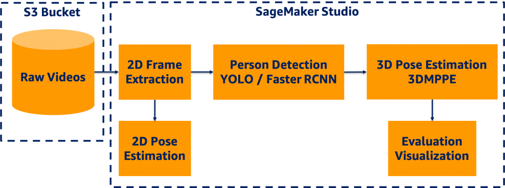
SM Studio offers a broad range of features facilitating the development process, including easy access to data in Amazon S3, availability of compute capability, software and library availability, and an integrated development experience (IDE) for ML applications.
First, we read the video data from the S3 bucket and extracted the 2D frames in a portable network graphics (PNG) format for frame-level development. We used YOLOv3 object detection to generate a bounding box of each person detected in a frame. For more information, see Benchmarking Training Time for CNN-based Detectors with Apache MXNet.
Next, we passed the frames and corresponding bounding box information to the 3D pose estimation model to generate the key points for evaluation and visualization. We applied a 2D pose estimation technique to the frames, and we generated the key points per frame for development and evaluation. The following sections discuss the details of each module in the 3D pipeline.
Data preprocessing
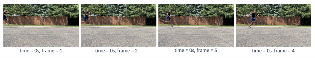
The first step was to extract frames from a given video utilizing OpenCV as shown in the following figure. We used two counters to keep track of time and frame count respectively, because videos were captured at different frames per second (FPS) rates. We then stored the sequence of images asvideo_name + second_count + frame_countin PNG format.
Object (person) detection
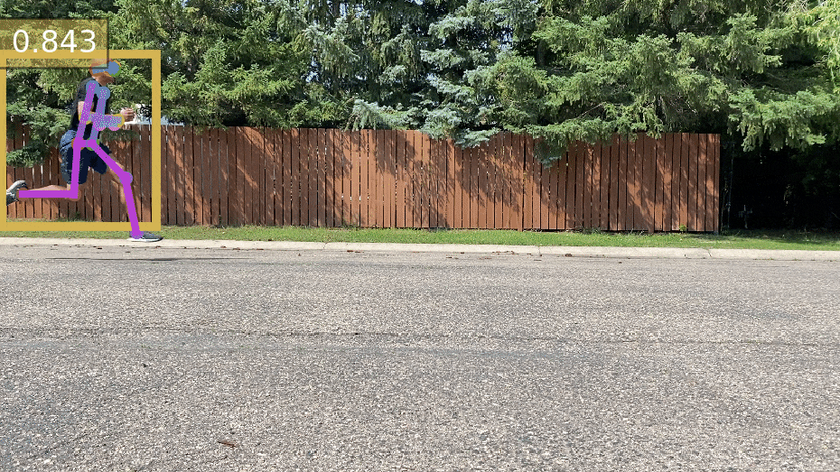
We employed YOLOv3 pretrained models based on the Pascal VOC dataset to detect persons in frames. For more information, see Deploying custom models built with Gluon and Apache MXNet on Amazon SageMaker. The YOLOv3 algorithm produced the bounding boxes shown in the following animations (the original images are resized to 910×512 pixels).
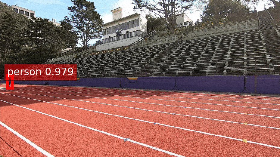
We stored the bounding box coordinates in a CSV file, in which the rows indicated the frame index, bounding box information as a list, and their confidence scores.
2D pose estimation
We selected ResNet-18 V1b as the pretrained pose estimation model, which considers a top-down strategy to estimate human poses within bounding boxes output by the object detection model. We further reset the detector classes to include humans so that the non-maximum suppression (NMS) process could be performed faster. The Simple Pose network was applied to predict heatmaps for key points (as in the following animation), and the highest values in the heatmaps were mapped to the coordinates on the original images.
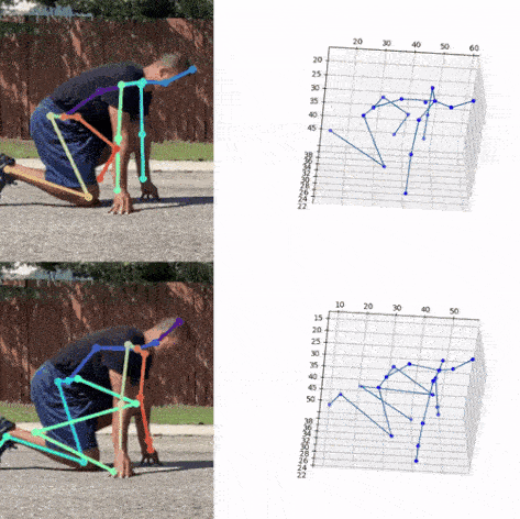
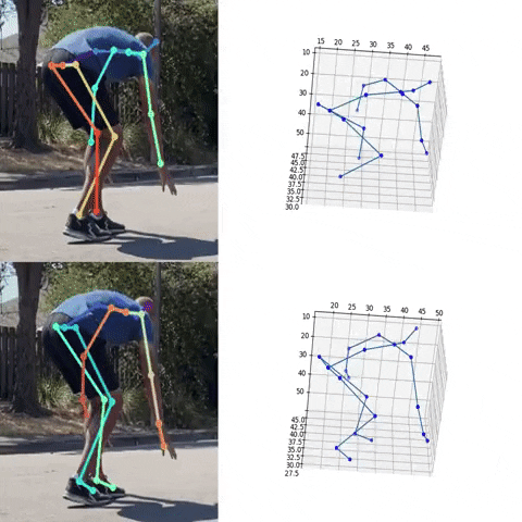
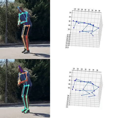
3D pose estimation
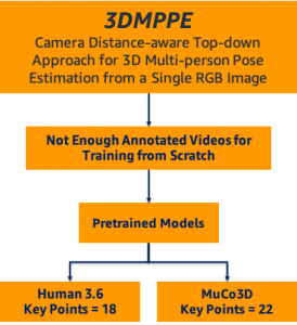
We employed a state-of-the-art 3D pose estimation algorithm encompassing a camera distance-aware top-down method for multi-person per RGB frame referred to as 3DMPPE (Moon et al.). This algorithm consisted of two major phases:
- RootNet – Estimates the camera-centered coordinates of a person’s root in a cropped frame
- PoseNet – Uses a top-down approach to predict the relative 3D pose coordinates in the cropped image
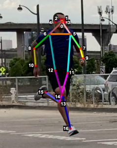
Next, we used the bounding box information to project the 3D coordinates back to the original space. 3DMPPE offered two pretrained models trained using Human36 and MuCo3D datasets (for more information, see the GitHub repo), which included 17 and 21 key points, respectively, as illustrated in the following animations. We used the 3D pose coordinates predicted by the two pretrained models for visualization and evaluation purposes.
Evaluation
To evaluate the 2D and 3D pose estimation models’ performance, we used the 2D pose (x,y) and 3D pose (x,y,z) coordinates for each joint generated for every frame in a given video. The number of key points varied based on the datasets; for instance, the Leeds Sports Pose Dataset (LSP) includes 14, whereas the MPII Human Pose dataset, a state-of-the-art benchmark for evaluating articulated human pose estimation referring to Human3.6M, includes 16 key points. We used two metrics commonly used for both 2D and 3D pose estimation, as described in the next section on evaluation. In our implementation, our default key points dictionary followed the COCO detection dataset, which has 17 key points (see the following image), and the order is defined as follows:
KEY POINTS = {
0: "nose",
1: "left_eye",
2: "right_eye",
3: "left_ear",
4: "right_ear",
5: "left_shoulder",
6: "right_shoulder",
7: "left_elbow",
8: "right_elbow",
9: "left_wrist",
10: "right_wrist",
11: "left_hip",
12: "right_hip",
13: "left_knee",
14: "right_knee",
15: "left_ankle",
16: "right_ankle"
}
Mean per joint position error
Mean per joint position error (MPJPE) is the Euclidean distance between ground truth and a joint prediction. As MPJPE measures the error or loss distance, and lower values indicate greater precision.
We use the following pseudo code:
- Let G denote
ground_truth_jointand preprocess G by:- Replacing the null entries in G with [0,0] (2D) or [0,0,0] (3D)
- Using a Boolean matrix B to store the location of null entries
- Let P denote
predicted_joint matrix, and align G and P by frame index by inserting a zero vector if any frame doesn’t have results or is unlabeled - Compute element-wise Euclidean distance between G and P, and let D denote distance matrix
- Replace Di,j with 0 if Bi,j
- Mean per joint position is the mean value of each column of Ds,tDi,j ≠ 0
The following figure visualizes an example of video’s per joint error, a matrix with dimension m*n, where m denotes the number of frames in a video and n denotes the number of joints (key points). The matrix shows an example of a heatmap of per joint position error on the left and the mean per joint position error on the right.
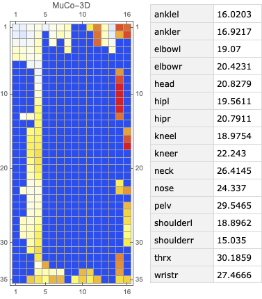
The following figure visualizes an example of video’s per joint error, a matrix with dimension m*n , where m denotes the number of frames in a video and n denotes the number of joints (key points). The matrix shows an example of a heatmap of per joint position error on the left and the mean per joint position error on the right.
Percentage of correct key points
The percentage of correct key points (PCK) represents a pose evaluation metric where a detected joint is considered correct if the distance between the predicted and actual joint is within a certain threshold; this threshold may vary, which leads to a few different variations of metrics. Three variations are commonly used:
- PCKh@0.5, which is when the threshold is defined as 0.5 * head bone link
- PCK@0.2, which is when the distance between the predicted and actual joint is < 0.2 * torso diameter
- 150mm as a hard threshold
In our solution, we used the PCKh@0.5 as our ground truth XML data containing the head bounding box, which we can use to compute the head-bone link. To the best of our knowledge, no existing package contains an easy-to-use implementation for this metric; therefore, we implemented the metric in-house.
Pseudo code
We used the following pseudo code:
- Let G denote ground-truth joint and preprocess G by:
- Replacing the null entries in G with [0,0] (2D) or [0,0,0] (3D)
- Using a Boolean matrix B to store the location of null entries
- For each frame Fi, use its bbox Bi=(xmin,ymin,xmax,ymax) to compute each frame’s corresponding head-bone link Hi , where Hi=((xmax-xmin)2+(ymax-ymin)2)½
- Let P denote predicted joint matrix and align G and P by frame index; insert a zero tensor if any frame is missing
- Compute the element-wise 2-norm error between G and P; let E denote error matrix, where Ei,j=||Gi,j-Pi,j||
- Compute a scaled matrix S=H*I, where I represents an identity matrix with the same dimension as E
- To avoid division by 0, replace Si,j with 0.000001 if Bi,j=1
- Compute scaled error matrix Si,j=Ei,j/Si,j
- Filter out SE with threshold = 0.5, and let C denote the counter matrix, where Ci,j=1 if SEi,j<0.5 and Ci,j=0 elsewise
- Count how many 1’s in C*,j as c⃗ and count how many 0’s in B*,j as b⃗
- PCKh@0.5=mean(c⃗/b⃗)
In the sixth step (replace Si,jwith 0.000001 if Bi,j=1), we set up a trap for the scaled error matrix by replacing 0 entries with 0.00001. Dividing any number by a tiny number generates an amplified number. Because we later used > 0.5 as a threshold to filter out incorrect predictions, the null entries were excluded from the correct prediction because it was way too large. We subsequently counted only the not null entries in the Boolean matrix. In this way, we also excluded the null entries from the whole dataset. We proposed an engineering trick in this implementation to filter out null entries from either unlabeled key points in the ground truth or the frames with no person detected.
Video alignment
We considered two different camera configurations to capture video data from athletes, namely the line and box setups. The line setup consists of four cameras placed along a line while the box setup consists of four cameras placed in each corner of a rectangle. The cameras were synchronized in the line configuration and then lined up at a predefined distance from each other, utilizing slightly overlapping camera angles. The objective of the video alignment in the line configuration was to identify the timestamps connecting consecutive cameras to remove repeated and empty frames. We implemented two approaches based on object detection and cross-correlation of optical flows.
Object detection algorithm
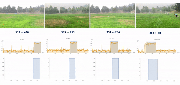
We used the object detection results in this approach, including persons’ bounding boxes from the previous steps. The object detection techniques produced a probability (score) per person in each frame. Therefore, plotting the scores in a video enabled us to find the frame where the first person appeared or disappeared. The reference frame from the box configuration was extracted from each video, and all cameras were then synchronized based on the first frame’s references. In the line configuration, both the start and end timestamps were extracted, and a rule-based algorithm was implemented to connect and align consecutive videos, as illustrated in the following images.
The top videos in the following figure show the original videos in the line configuration. Underneath that are person detection scores. The next rows show a threshold of 0.75 applied to the scores, and appropriate start and end timestamps are extracted. The bottom row shows aligned videos for further analysis.
Moment of snap
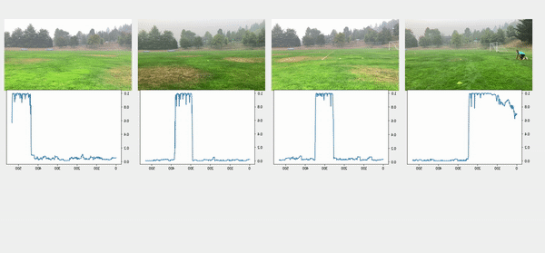
We introduced the moment of snap (MOS) – a well-known alignment approach – which indicates when an event or play begins. We wanted to determine the frame number when an athlete enters or leaves the scene. Typically, relatively little movement occurs on the running field before the start and after the end of the snap, whereas relatively substantial movement occurs when the athlete is running. Therefore, intuitively, we could find the MOS frame by finding the video frames with relatively large differences in the video’s movement before and after the frame. To this end, we utilized density optical flow, a standard measure of movement in the video, to estimate the MOS. First, given a video, we computed optical flow for every two consecutive frames. The following videos present a visualization of dense optical flow on the horizontal axis.
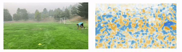
We then measured cross-correlation between two consecutive frames’ optical flows, because cross-correlation measures the difference between them. For each angle’s camera-captured video, we repeated the algorithm to find its MOS. Finally, we used the MOS frame as the key frame for aligning videos from different angles. The following video details these steps.
Conclusion
The technical objective of the work demonstrated in this post was to develop a deep-learning based solution producing 3D pose estimation coordinates using 2D videos. We employed a camera distance-aware technique with a top-down approach to achieve 3D multi-person pose estimation. Further, using object detection, cross-correlation, and optical flow algorithms, we aligned the videos captured from different angles.
This work has enabled coaches to analyze 3D pose estimation of athletes over time to measure biomechanics metrics, such as velocity, and monitor the athletes’ performance using quantitative and qualitative methods.
This post demonstrated a simplified process for extracting 3D poses in real-world scenarios, which can be scaled to coaching in other sports such as swimming or team sports.
If you would like help with accelerating the use of ML in your products and services, please contact the Amazon ML Solutions Lab program.
References
Moon, Gyeongsik, Ju Yong Chang, and Kyoung Mu Lee. “Camera distance-aware top-down approach for 3d multi-person pose estimation from a single RGB image.” In Proceedings of the IEEE International Conference on Computer Vision, pp. 10133-10142. 2019.
About the Author
 Saman Sarraf is a Data Scientist at the Amazon ML Solutions Lab. His background is in applied machine learning including deep learning, computer vision, and time series data prediction.
 Amery Cong is an Algorithms Engineer at Intel, where he develops machine learning and computer vision technologies to drive biomechanical analyses at the Olympic Games. He is interested in quantifying human physiology with AI, especially in a sports performance context.
 Ashton Eaton is a Product Development Engineer at Intel, where he helps design and test technologies aimed at advancing sport performance. He works with customers and the engineering team to identify and develop products that serve customer needs. He is interested in applying science and technology to human performance.
 Jonathan Lee is the Director of Sports Performance Technology, Olympic Technology Group at Intel. He studied the application of machine learning to health as an undergrad at UCLA and during his graduate work at University of Oxford. His career has focused on algorithm and sensor development for health and human performance. He now leads the 3D Athlete Tracking project at Intel.
 Nelson Leung is the Platform Architect in the Sports Performance CoE at Intel, where he defines end-to-end architecture for cutting-edge products that enhance athlete performance. He also leads the implementation, deployment and productization of these machine learning solutions at scale to different Intel partners.
 Suchitra Sathyanarayana is a manager at the Amazon ML Solutions Lab, where she helps AWS customers across different industry verticals accelerate their AI and cloud adoption. She holds a PhD in Computer Vision from Nanyang Technological University, Singapore.

Wenzhen Zhu is a data scientist with the Amazon ML Solution Lab team at Amazon Web Services. She leverages Machine Learning and Deep Learning to solve diverse problems across industries for AWS customers.